

August 2004 - working on Engine #1
- Jul 22, 2017
- 7 min read
8/3/2004:
Today, parts from Five Star Ford in AZ arrived and a most crucial part was finally in my posession: the camshaft thurst plate. With this plate and associated bolts, I can finally install the CompCam permenantly. And with this, I can also button up the timing chain cover and oil pan. More on this most likely this weekend. Other parts were also in the package which are no less important but the thrust plate is really what will start the engine assembly process:

Here, I've completed installation of the thrust plate; hex bolts were torque to 10 ft-lbs. with some Loctite Red for good measure. then the cam sprocket was installed with the ARP bolt torqued to 43 ft-lbs. (Tom's book indicates 40-45 ft-lbs.) Again, a dab of Loctite Red here for insurance as Tom says. :) I took a measurement of the end-play of the cam assembly and came up with just barely under .004". I checked the Chilton's manual and the "maximum" end-play is .009" so I'm well within specifications.. And CAREFUL attention was paid to the orientation of the thrust plate. Actually, it's pretty obvious since you can see where the oil channel meets the oil hole nearby.
*EDIT* 7/6/2006 - I have applied the same measuring technique on the new CHP 347 Stroker that replaced this motor so I decided to keep these particular pictures.

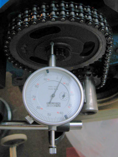
Sorry for the poor quality; it was getting to dusk when the photo was taken w/o flash (to avoid washing out the dial indicator.)
8/6/2004:
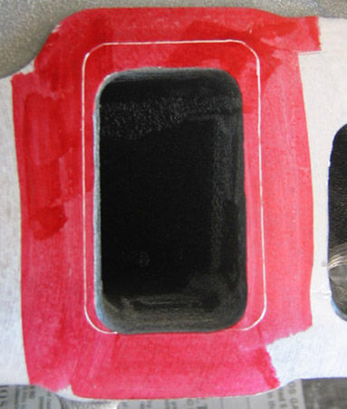
I worked a little bit on aligning the intake manifold to the Fel-Pro gaskets and marking various spots along the perimeter of intake where the gasket was exposed. This involved first dabbing a bit of silione on the backside of each gasket and setting them where I need them on the cylinder heads. Then I mounted and torqued down the intake manifold and made several marks all around the intake.
Then I removed the intake and flipped it on one side and matched up gasket marks with the intake and clamped it down, and scribed my lines. Then flipped it to the other side with the opposite gasket and repeated the process. At this point, I'm ready to begin the port matching. We'll see how this goes this weekend. A big THANKS to HankL for detailing this process. It made perfect sense to do it this way.
8/7/2004:
I started the porting process but I can now say that people who do this for a living, definetly EARN their money. This is not easy work. Let me preface this with a couple of facts: 1) I've never done this before and 2) I do have a new Ingersoll-Rand #307 die grinder, along with a Standard Abrasives Full porting kit. After reading the SA manual over and over again for the last 2-3 months, I felt I can do a decent job. After 2 hours on just ONE port, I still think I can do this but now I understand why it takes some head guy's a few weeks. Despite what people might say about aluminum, it's NOT that soft. It's probably soft compared to iron and I'd hate to port something that's harder than what I've already doing.
I started with the Hurricane Intake first on the logic that if I ruined this, it wouldn't cost as much as a cylinder head! I did start off wrong by using the porting "stone" and even the stone that came with the die grinder; it got me started but they both gunked up pretty good after awhile, however, I found the most coarse drum in the SA kit worked best for removing the large areas; of course I spent a good 30 minutes using a stone before I realized this! The next 1.5 hours was all grinding in and around this port. Here are a few pics I took. I have a LOT of work ahead:

As you can see, the port on the left needs a bit more work but it's basically there. I'm purposly leaving the intakes just slightly smaller than the gasket. From what I've been told, it's better to be on the smaller side on the intake, than larger. The second port should be a little faster now that I've got the hang of the die grinder.
8/14/2004:
Today, I began on the intake manifold in earnest and by 5:00PM, I finally finished one side:
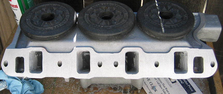

As you can see, it's not the most professional but overall, it does the job. The 'floor' of each port (upside down on the pictures) were lower than the gasket but not by much. I will trim just a very slight amount off the gasket on each port.
What I've learned today is that even with a cabide die-cutter, this is still one of those operations that simply takes time to do. There is no shortcut for the home DIY with the tools I have ( 35 gallon compressor and 1/3hp die-grinder ). I figure a professional shop has a compressor many times larger than mine and a die-grinder with much more hp, not to mention, he's a pro and would do an imensley better job than I and probably in 1/2 the time. However, by doing this, I felt I learned a great deal about how it should be done and it's not a very intimidating task once you've started on a few. I may also go back and refine some of the area's that need more blending but these ports are now capable of flowing a little bit better.
8/15/2004:
I was telling my adventures on FFCobra.com and TMC recommended I use WD40 to reduce build up. When I did this, I discovered something that should of already been evident when I drill into metal: lubrication helps cutting! I spent only 2 hours to remove the same amount of material that took me 4.5 hours yesterday to do, simply by dipping the cabide cutters into a cap full of WD40 often. And 90% of this was done with the electric drill. Spent about another 20-30 min. with the abrasives before calling it done. I washed off the red maker and then washed the entire manifold. Again, not the most professional but I believe there will be some gains once the cylinder heads are completed. I did get a shot of the plenum when mated to the cylinder heads; cylinder #3's intake can be seen here:


8/18/2004:
After a few days of resting the hands and forearms, I went back to work. I removed the cylinder heads and all of the ARP head studs/washers/bushings/nuts and using a parts washer, I removed most of the oil and crud. I'll finish off the threads and nuts later on, in some brake cleaner; the citrus solvent is "ok" for general washing but it doesn't really get down into the threads, even though I was using a variety of steel bristle brushes.
I did manage to find an hour this evening and finished polishing all of the exhaust ports; here's a shot that was typical of the exhaust port:

Some carbon deposit; walls are somewhat rough but smoother than the intakes. About 10 minutes on each head produced this:

The
photo is somewhat deceiving. It's the evening sun hitting it at a good angle :)
8/19/2004:
Received another little package from Summit Racing:
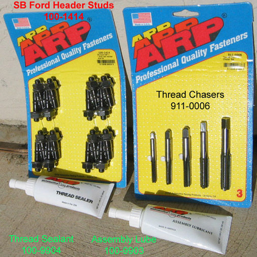
The thread sealer and assembly lube will be very neccessary when the heads go on for the final time. The ARP lube is recommended due to it's execellent anti-friction properties. When the head studs are torqued down it will actually take LESS torque to apply the same clamping force as it would if I use 30wt. motor oil. The specified torque for a 7/16" stud with ARP special moly lube, is 70 ft-lbs. If I use 30wt. oil, I must use 85 ft-lbs. to achieve the same clamping force. This is a 17% increase in torque.
The thread chasers are reportedly better to use than a "tap" as it is not designed to "cut" the threads. Re-cutting the threads, according to ARP, is not recommended as they claim it will "weaken" the threads by removing more material. Sounded good to me.
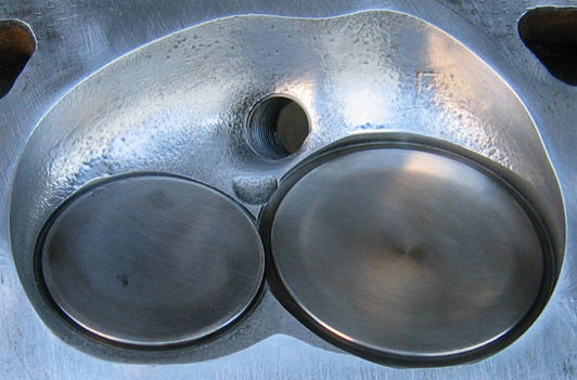
I also made a first pass on the bowls of one cylinder head. I did a decent job or getting rid of "most" of the high spots while trying not to change the overall chamber volume. I used a normal drill but on the next head, I will used my die grinder to see if it really makes a difference or not.
BEFORE:

AFTER:

8/22/2004:
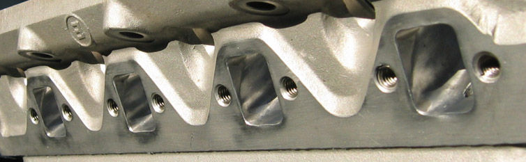
I had a few hours today and decided to tackle the cylinder head. Since there isn't as much material to remove as compared to the intake, the time was about 1.5 hours to finish the 4 intakes ports on one cylinder head. All of the bowls were also polished up:


The head was cleaned up and I chased all of the threads, however, one of the helicoils on the exhaust header side had worked itself out a bit when the thread chasing tool had got hung up on something. It appears that at this point, I will need a helicoil insertion tool. The helicoil itself seems fine.

On the left is the picture of cylinder intake port #6 before porting (see 8/15/04 entry); on the right, after.
8/25/2004:
Spent an hour putting on the valves, valve springs, seals, valve locsk and retainers. I discovered that CompCams gave me only enough valve locks for 10 valves; I'm short 6 pair. Email sent out to Mike Forte. Might need to involve CompCams as well.
I had also bought a helicoil tool with extra 3/8-14 coils. Repair was extremely quick!
The driver side head looks a bit like it did when I first bought it but it is now port matched and the bowls are polished and the valve springs are much stronger than stock!
8/26/2004:
I went to the CompCam site to investigate the valve spring "install" height issue. According to their website, I need to measure from the floor of the vavle spring seat on the cylinder head, to right under the retainer. Here's the link to CompCam's diagram.
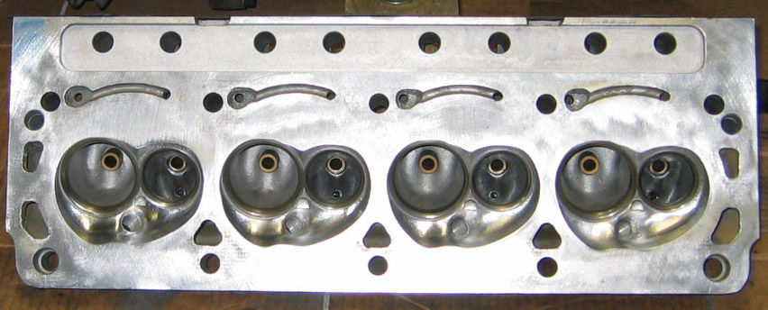
8/31/2004:
What a month August has been. In terms of progress this month has been one of the most productive to date. I'm finishing this journal with a picutre of cylinder head number two which I've started working on. Polishing this time around took only 1 hour! Port matching will likely happen this Labor Day Weekend.

Comments